Views: 128 Author: Site Editor Publish Time: 2026-09-19 Origin: Site
The shift from hard-plumbed infrastructure to modular systems requires extremely reliable fluid management. Industrial manufacturing floors and enterprise data centers increasingly rely on highly serviceable networks. Unfortunately, routine maintenance downtime costs these operations heavily in lost daily productivity. Hazardous fluid spills and sudden system depressurization routinely cause severe hardware damage. Furthermore, draining and refilling massive fluid lines consumes hours of critical engineering time.
Fortunately, facility operators can avoid these costly failures entirely. Quick disconnects bridge the vital gap between permanent plumbing and dynamic operational flexibility. They allow technicians to perform immediate line separation. You experience practically zero fluid loss during the process. You completely prevent dangerous air inclusion in sensitive hydraulic loops. This article explores how these precise mechanical components safeguard your critical systems. We will cover core coupling mechanics, standard versus specialized designs, and advanced IT cooling applications. You will learn how to specify the exact hardware your complex environment demands.
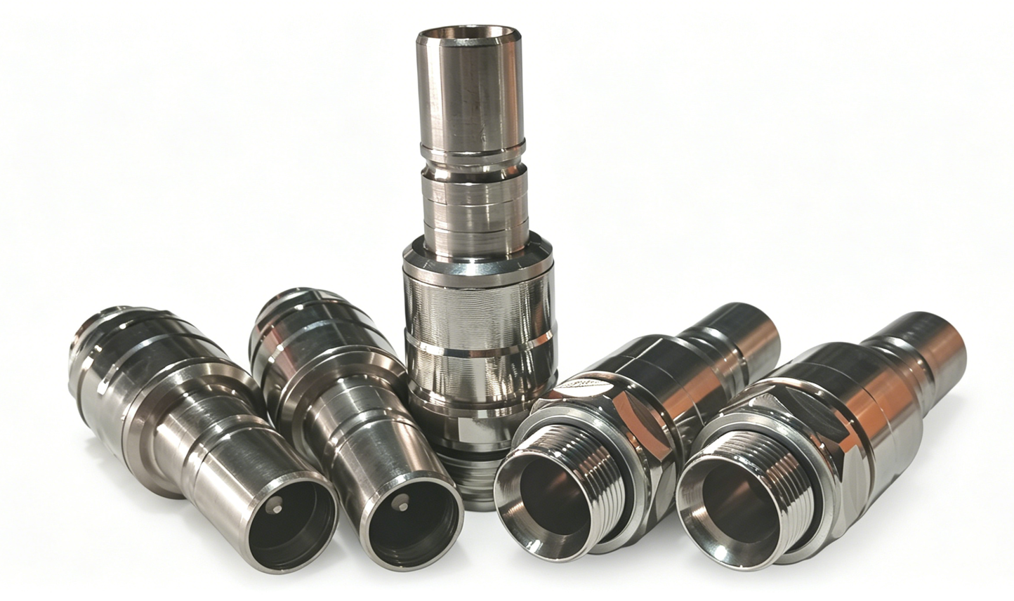
Definition: Mechanical fittings designed for rapid connection and disconnection of fluid lines without specialized tools.
Core Variations: Selection ranges from standard straight-through designs to dry break quick disconnect systems that prevent virtually all fluid loss.
Critical Specs: Sizing must account for acceptable pressure drop (Cv), fluid compatibility, operating temperature, and peak system pressure.
Modern Applications: Beyond traditional hydraulics, high-spec variants are now critical infrastructure for server thermal management (e.g., liquid cooling connector applications).
To specify fluid handling systems correctly, you must first understand the fundamental anatomy. A standard fitting features two primary mating halves. Engineers refer to the male end as the plug or nipple. They call the female receptacle the socket or body. When you push them together, they lock instantly. Manufacturers employ several distinct locking mechanisms for different operational environments. Ball-latch designs utilize a ring of stainless steel balls. These balls drop into a retaining groove on the plug. This mechanism offers incredibly smooth engagement. Threaded locks require manual twisting. They easily withstand severe vibration and high-pressure pulsation. Pin-latch styles provide positive tactile feedback. Technicians know instantly when the connection firmly secures.
Inside these rigid external bodies, highly specialized valves control all fluid flow. A successfully specified quick disconnect coupling must dramatically reduce Mean Time To Repair (MTTR). It must simultaneously maintain absolute system integrity. Industrial pipelines experience violent, dynamic pressure cycles daily. These sudden pressure spikes test mechanical connections constantly. You need hardware capable of surviving this repeated physical stress without degrading.
Engineers establish a strict performance baseline by differentiating between internal valving designs. Single-shutoff valves close only the socket side upon disconnection. The plug side remains completely open. Double-shutoff designs seal both halves instantly. They utilize internal springs to snap valves shut before the main seal breaks. Non-spill options push this engineering concept even further. They physically eliminate the internal dead space between the mating faces.
Fluid management requires distinct approaches based on overall system criticality. You must evaluate standard solutions against specialized non-spill technology carefully.
Standard double-shutoff fittings typically utilize traditional poppet valves. These valves feature a conical or flat head sitting heavily against a machined internal seat. These units remain highly economical. They boast widespread global availability. You will find them highly suitable for many non-hazardous fluids. Basic facility water loops and standard pneumatic lines use them extensively. However, their internal geometry creates an inherent design flaw. It leaves a small physical gap between the two poppets before full disconnection. This gap traps a small volume of fluid. Spillage inevitably occurs upon separation. This single drop might seem minor initially. However, fluid inclusion accumulates over multiple maintenance cycles. It creates dangerous slip hazards on factory floors.
You can eliminate these issues completely by upgrading your hardware. The dry break quick disconnect completely revolutionizes modern fluid handling. It utilizes an advanced flush-face valve design. When disconnected, the internal valve faces sit perfectly flush with the outer coupling body. This precise mechanism eliminates the dangerous dead space between the male and female halves. The mating process actively wipes the faces clean during connection.
The business outcome proves substantial for facility operators. This technology actively prevents hazardous environmental contamination. It protects sensitive surrounding electronics from catastrophic moisture damage. Furthermore, it firmly mitigates air inclusion. Trapped air severely degrades thermal performance. It causes destructive cavitation in expensive fluid pumps. Flush-face technology keeps your hydraulic and cooling loops completely pure.
Table: Standard Double-Shutoff vs. Flush-Face Technology
Feature | Standard Double-Shutoff | Dry Break (Flush-Face) |
|---|---|---|
Valve Mechanism | Conical or flat poppet valves | Flush-face wiping design |
Spillage Volume | Low (Drops per disconnect) | Near-zero (Effectively dry) |
Air Inclusion | Moderate risk upon connection | Virtually eliminated |
Ideal Applications | General pneumatics, basic water lines | Electronics cooling, hazardous chemicals |
High-density compute environments are changing at breakneck speed. Rack power densities now routinely exceed traditional air cooling limits. Modern processors and AI accelerators run incredibly hot. Facilities must transition aggressively to direct-to-chip liquid cooling systems. This massive shift in thermal management requires highly specialized plumbing hardware. Standard industrial fittings simply fail in these sterile, high-stakes IT environments.
Enter the IT-grade hardware solution. A robust liquid cooling connector handles incredibly strict operational requirements. It must deliver a remarkably low pressure drop. Fluid must flow smoothly to maintain maximum thermal efficiency. It requires absolutely zero spillage during routine hot-swapping procedures. Technicians often swap modular blade servers while the rack remains fully powered. Blind-mate capabilities are also frequently essential in these tight spaces. Technicians push heavy server chassis into racks blind. The rear manifold connections must align and engage flawlessly without any visual confirmation.
The fluid loop architecture relies heavily on centralized distribution. The Coolant Distribution Unit drives both the primary and secondary loops. A highly reliable CDU quick disconnect links this central pumping unit to the main rack manifolds seamlessly. It handles massive fluid flow rates continuously. It easily withstands continuous vibration from the heavy internal CDU pumps.
Standardization drives the modern data center industry forward. Hyperscale operators demand total vendor neutrality. They require seamless interoperability across all hardware platforms. Implementing an OCP compliant coupling answers this business case perfectly. The Open Compute Project (OCP) outlines strict physical geometries. It mandates highly specific performance parameters. Compliance ensures baseline safety across global hyperscale facilities. It firmly prevents catastrophic fluid leaks near incredibly expensive silicon chips.
How do you choose the correct mechanical component for your specific application? You must follow a rigorous engineering evaluation framework. Specifying the wrong fitting leads to immediate system failure. Follow these critical steps during your initial design phase.
Calculate Flow Rate and Pressure Drop (ΔP): You must calculate the required flow coefficient (Cv). The Cv value indicates exactly how much fluid passes through the valve at a specific pressure drop. Restrictive fittings choke your fluid velocity. They severely bottleneck overall system performance. Never overwork your facility pumps. High pressure drops force pumps to consume more electrical power and fail prematurely.
Verify Material and Fluid Compatibility: Metals and plastics react differently to synthetic fluids. Housing materials include standard brass, passivated stainless steel, lightweight aluminum, or engineered plastics. You must match the body material to the surrounding environment. Next, evaluate your elastomers carefully. The internal O-rings do the hardest mechanical work. You must pair EPDM, FKM (Viton), or Nitrile to your specific fluid chemistry. Hydraulic oil degrades EPDM instantly. Glycol-water mixtures require distinct chemical resistance. Dielectric fluids demand highly specific synthetic seal materials.
Evaluate Operating Pressures: Determine your maximum expected working pressure. Compare this against the manufacturer burst pressure rating. Standard engineering practice dictates a 4:1 safety margin for hydraulic systems. Account for dangerous system surges. Fast-acting solenoid valves create sudden pressure spikes. This hydraulic shock, commonly known as water hammer, destroys under-specced fittings. Select metal bodies capable of safely absorbing these violent kinetic impacts.
Theoretical engineering often clashes with harsh field maintenance realities. What goes wrong in actual deployment? Improper fluid matching destroys internal sealing components. Extreme temperature cycling degrades metallic materials rapidly. These harsh environmental factors lead directly to seal swelling. The rubber expands abnormally and binds the internal locking mechanism. Embrittlement follows shortly after. The seals harden, crack, and fail. Eventually, catastrophic leakage occurs across the facility floor.
Cross-connection hazards pose another massive operational risk. Technicians navigate incredibly complex fluid manifolds daily. In a dense server rack, dozens of identical hoses sit mere inches apart. Operators might easily connect the wrong fluid lines during a rushed shift. Mitigation requires deliberate, foolproof design choices. You should implement strict mechanical keying protocols. Keying utilizes unique physical profiles on the plug and socket. It physically prevents incorrect mating. Visual color-coding systems add another critical safety layer. Anodized red and blue rings guide the technician instantly to the correct hot or cold loop.
You must also carefully consider side-load stress. Severe mechanical stress plagues tight routing environments. Heavy, fluid-filled hoses pull unevenly on the connection joint. This side-load acts as a mechanical lever arm. It physically compromises the external locking sleeve. It throws internal valve alignment completely out of specification. The poppets fail to seat properly against the O-rings. You must support hose runs properly with rigid structural clamps. Always avoid sharp bend radii near the coupling body.
You must base your initial selection heavily on fluid compatibility. Check the maximum operating pressure first. These two metrics instantly eliminate unsuitable hardware from your list. Next, narrow down your choices by required flow coefficient (Cv). Factor in your specific allowable spillage tolerances. Finally, solidify your exact choice based on strict industry compliance. International ISO standards and open OCP specifications dictate safety levels. They guide your procurement effectively and reduce long-term risk.
Never rush the final procurement phase. We strongly recommend acquiring 3D CAD models early in the design cycle. Use these digital files for detailed spatial validation. Check your clearance tolerances physically. Request physical sample couplings directly from your chosen manufacturer. Conduct rigorous physical pressure-drop testing in your own lab. Verify the tactile feel of the locking mechanism. Complete these vital steps before you authorize full-scale facility procurement.
A: A standard fitting provides a permanent or semi-permanent connection requiring wrenches, thread sealant, and full line draining. A quick disconnect focuses entirely on the speed of serviceability. It features integrated internal valving. This valving halts fluid flow automatically upon separation. You eliminate the need to drain lines. You never need heavy tools for routine maintenance.
A: These terms often overlap in casual engineering conversation. However, a distinct technical difference exists. "Dry break" refers specifically to a performance outcome. It guarantees near-zero fluid spillage during physical separation. Flat-face or flush-face describes the actual physical mechanical design. Flush-face designs successfully achieve this dry break performance standard.
A: The Open Compute Project (OCP) guarantees extremely strict manufacturing tolerances. OCP compliance dictates acceptable pressure drop, operational reliability, and exact physical form factor. Standardization reduces restrictive vendor lock-in. It allows operators to source interchangeable parts safely. Ultimately, this compliance safeguards incredibly expensive IT hardware from disastrous fluid leaks.